3d Modelling Paradata
If part of the purpose of the fresco was to evoke a theatre-like structure, how far can we assume it to have been based on the kind of temporary stage sets that Romans built in reality, and how far on fantasy? Alan Little, approaching this fresco as if it might provide a direct echo of actual theatre architecture, adapted its design to incorporate side doors as means of access.
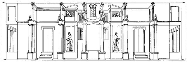
Alan Little's hypothetical reconstruction of a Roman stage based on the fresco. Roman Perspective and the Ancient Stage, Star Press 1971.
Our approach, by contrast, is based on the belief that one can not attempt to assess the value of such frescoes as theatre-historical sources without understanding them, first and foremost, as frescoes. That requires an attentiveness to how Roman fresco art blended influences from not one, but multiple sources into its own distinctive "visual vernacular" over time and, in particular, detailed attention to compositional techniques, with which this study is primarily concerned.
As mentioned in the wall painting analysis section, many problems occur in the interpretation of the wall painting regarding what is envisaged as "real" and what is not. Also, due to the multiple lines of perspective incorporated within
the scene, the fresco structure depicted is painted using many
conflicting angles, impossible in reality.
An exact 3d extrapolation based on the
painted architecture would therefore be very difficult to create. The two main options for a "virtual" reconstruction include:
(1) A visualisation of the architecture that would replicate the multiple lines of perspective, this would involve constructing architectural elements at various conflicting angles to each other. When viewed from the front and a similar viewpoint of that in the composed in the fresco, the virtual reconstruction should look comparable to the painted architecture. However, when seen from any other position it would be clear that the virtual reconstruction would be an irregular and architectural impossible structure, and that it would be unlikely to stand up if actually built in real life.
(2) A visualisation of the stage set as a "realistic
structure". This would involve constructing the structure based on selected architectural elements within the fresco, ignoring architectural elements that have been distorted by perspective. The resultant 3d architecture may appear somewhat different to that depicted in the wall painting, but would employ corrected components for a feasible
free-standing architectural structure.
From a theatre-historical point of view, modelling the stage-like architecture as a realistic, corrected, architectural structure would give a far better understanding of its properties than if creating a fantastical structure which is already shown in the wall painting. Also, the process of modelling a corrected version of the structure may give clues as to why the idea of a "stage set" has been evoked in the way it has.
The 3d model was constructed in 3d Studio Max software by initially working on top of the reconstructed drawing by Klinkert as this clearly shows the architectural features of the wall painting. (Figure 1).
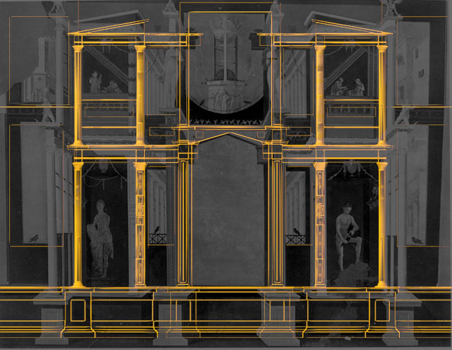
Figure 1. Overlay of 3d model onto wall painting.
The lower and upper central wall panels were used as the reference point for gauging the
width and height proportions of the structure; the rationale being that all elements of the structure, despite being distorted by perspective, join together on this back plane. The importance of this process can be seen in the positioning and proportions of the columns and bases in the corrected 3d model when overlaid onto the wall painting (Figure 2).
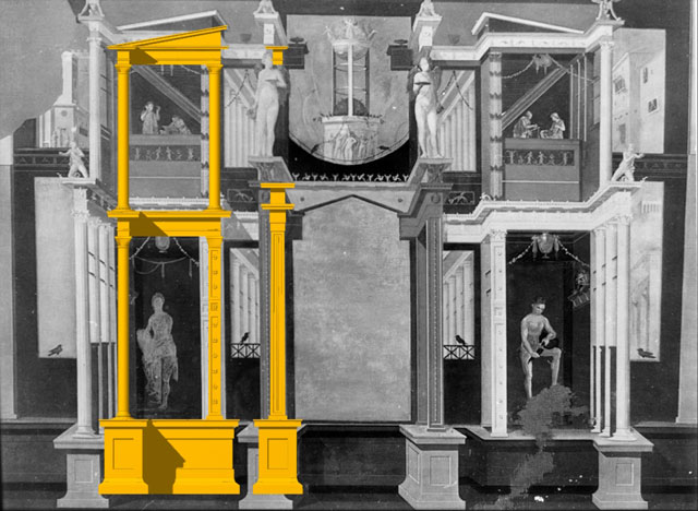
Figure 2. Showing frontal elevation rendering of 3d model overlaid onto the wall painting image.
In Figure 2, the left-hand side of the model has been "correctly" positioned ignoring corresponding elements of the painting that are distorted by perspectival foreshortening.
Determining the structural depth of individual elements within the architecture is more problematic, in particular the lower level of the wall painting because of its many lines of perspective. These produce irregular angles and give conflicting indications of the depth of structural elements.
An example of depth irregularities can be found in the lower left and right section of the structure. A row of three columns rests on an extended portion of the pulpitum linking to a recess which is roofed with an entablature, all of these elements connected as a single structural entity. The problem is that this entity alone incorporates six different lines of perspective creating many conflicting angles within the same part of the structure (Figure 3).
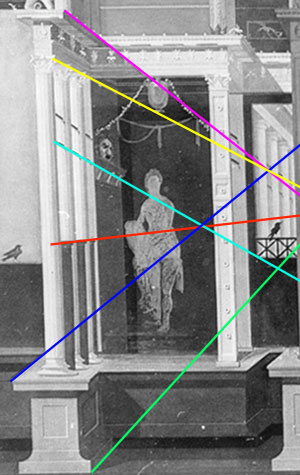
Figure 3. Showing perspectival problems relating to depth
It is also evident in this section of the wall painting that the row of columns appears gradually to lean outwards, thereby enabling the entablature to be deeper in depth than the pulpitum on which the columns rest. A closer inspection reveals, as well as perspectival problems, compositional problems that also produce inconsistent depth indicators.
Illustrated in Figure 4, below, the blue rectangle marker represents a frame around the edge of the pulpitum and entablature. The red line represents the edge and angle of the rear column. The top of the column is painted in front of the blue frame, but the column base is painted some distance behind the blue frame, creating a curious Escheresque effect.
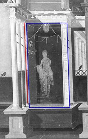
Figure 4. Showing structural irregularities due to composition
The leaning columns could be regarded as either a mistake in the composition or (more likely, given the coherence of the design as a whole) intentional artistry to emphasize certain features. Either way, if the design had adhered to life-like perspective, the extended pulpitum base would have disappeared out of the painting. Here, instead, it has been squashed into the composition, by pushing the column bases further back onto the pulpitum. This creates various knock-on effects in the same section of the structure and various perspectival tricks are used to compensate for this. The columns, for example, instead of leaning left appear to tilt forwards, creating a foreshortening effect (Figure 4).
Another knock-on effect can been seen in the depth of the pulpitum surfaces (Figure 5 - shown in red), which varies dramatically in an attempt to counterbalance perspectival distortions elsewhere. Illustrated in Figure 5, the bottom blue line shows how what is in fact a highly irregular architectural composition has been given a regular frame coterminous with the floor of the room. Above it, the bottom level of the pulpitum bases unrealistically align with the same even horizontal plane so that they, too, echo the regular line of the actual floor of the room. The top level of the pulpitum, however, has been painted "realistically" showing that the pulpitum bases extend outwards to different levels.

Figure 5. Unreliable measurements of depth
For the 3d visualisation, no accurate method can be used to formulate depth based solely on an analysis of the wall painting itself. The spatial depth of the 3d structure can therefore only be approximate based on a general likeness to that depicted in the fresco.
The depth of the stage architecture was notionally modelled to help with the fitting together of various interconnecting elements, in turn, creating a sense of realistic space to work from. In order to gauge the depth proper, virtual cameras were positioned in the 3d model to mimic the perspective of the wall painting. A virtual camera was positioned on the same axis as the vanishing point of the top level of the structure, and a virtual camera positioned to roughly coincide with the middle of the multiple perspective points on the lower level. Both cameras were then moved back along their axis until viewpoints were found that produced a likeness to what is seen in the wall painting. (Figure 6).
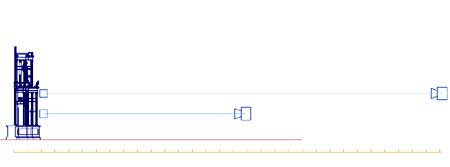
Figure 6. The final camera positions for the upper and lower levels of the structure.
A single light source was also positioned within the 3d model casting shadows onto the virtual architecture and adjusted to replicate the shadows seen on the fresco's architecture. Shadow information from the wall painting acted as a valuable guide to help fine-tune the depths of individual elements within the virtual structure. Colour information was then added to help make detailed like-for-like comparisons between model and fresco. A combination of re-adjusting individual elements within the model, based on shadow information and camera viewpoints, finally achieved a comparable likeness to that of the lower and upper levels of the architecture depicted in the wall painting (Figures 7-10).
A third virtual camera was then positioned central to the 3d structure and pulled back along its axis to create an overall rendering as if viewed with life-like perspective. The result shows the upper level remaining comparable to that in the wall painting, owing to the fact that the "regular" perspective used in the 3d model closely matches the perspective in the upper level of the wall painting.
The lower level, however, is inevitably different. When viewed with "regular" perspective the pulpitum extends much further than as seen in the wall painting, giving a clearer indication of just how much the fresco artist has forced the pulpitum area to fit into a regular compositional frame by creating many perspective points (Figure 11).
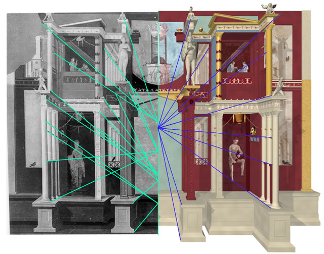
Figure 11. Comparison of wall painting and corrected 3d model viewed with "regular" perspective.
It is easy, now, to see how the segments of pulpitum that extend outwards in the wall painting have been forcefully squeezed to fit a single, horizontal base line so as to give the impression that the painted structure sits firmly on the actual floor of the room. With the fresco painted from floor to ceiling, and composed so as to seem somewhat bottom-heavy, the depicted structure gives viewer in the room a strong sense of real presence, despite what, on close examination, is revealed as a series of complex perspectival distortions.
The room in which the wall painting is situated is very small with a maxim viewing distance of 2.6 meters. If the artist had painted the structure with a single
point of perspective as used in the 3d visualisation (Figure
11), the upper level would look "normal" in relationship to the room but the lower level would look "abnormal" as though tilting
forward over the viewer. The closer one views the painting the worse the lower level would appear to tilt (Figure 12).
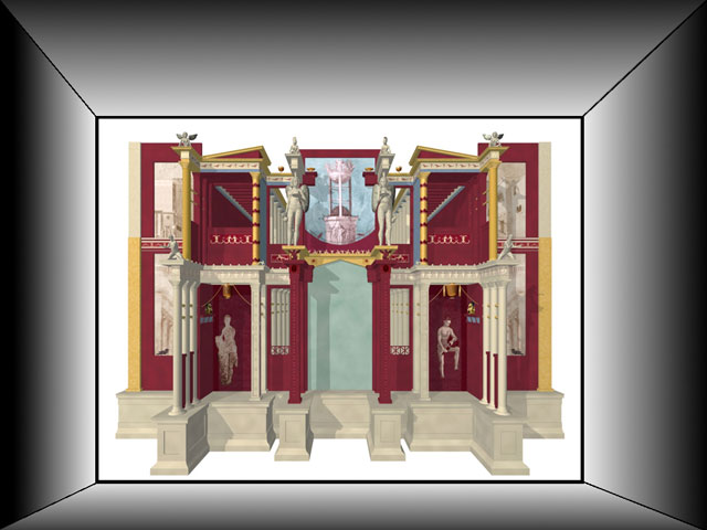
Figure 12. If viewed with single perspective in the context of the room the structure looks incorrect.
The viewing perspective within the context of room itself plays a major part in the interpretation of the fresco's perspectival techniques. For example, a painting that incorporates "real" perspective may appear "wrong" when viewed from a different perspectival plane within the room.
The artist has clearly realised the importance of the viewing perspective within the confines of the room by utilising an upper and lower level with separate perspective points intended to deceive the viewer into thinking the depicted structure is architecturally correct when in fact it is not (Figure 13).
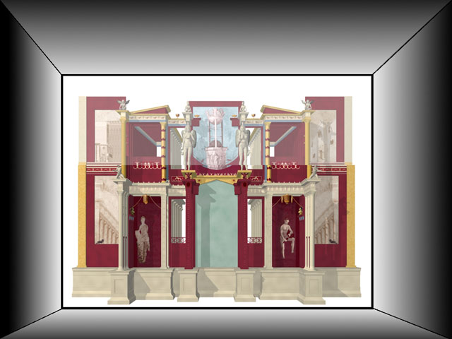
Figure 13. Combining two separate levels of perspective, when viewed in the context of the room the structure appears corrected.
The 3d modelling has thus far proceeded on the basis that a "real" architecture has "painted", flat panels, depicting "non real" elements, inserted within it (see wall painting analysis). When viewing the 3d structure from any viewpoint other than frontal perspective, one can really understand the spatial arrangement of the architecture and see just how the flat panels are affected by the viewers perspective (Figure 14).
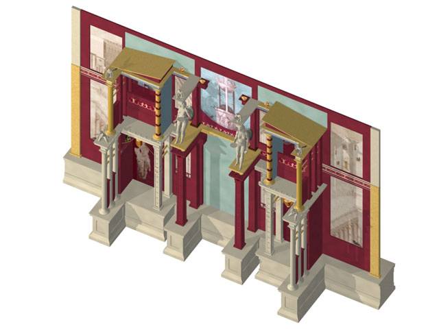
Figure 14. 3d "stage structure" viewed from above showing flat panels.
From a theatre-historical perspective, the architecture in the wall painting may have been painted to evoke two different viewing positions at an actual theatre performance. As already encountered with the creation of virtual cameras to compare and construct the upper and lower structure, these camera viewpoints may have some bearing on the relative viewing positions within a theatre (Figure 15).

Figure 15. The final camera positions for the upper and lower levels of the structure.
The inner apertures depicted in the wall painting that contain receding columns are a possible indication of this. The lower apertures contain only a few columns suggesting a view from the front of the lower cavea in the theatre. The upper apertures, by contrast, clearly contain more columns, suggesting a view from the back of the upper cavea. This is one possible reason why the architecture is divided into two distinct levels, and why the intercolumniation
within the colonnade is different in the upper section and lower
structure (Figure 16).
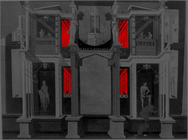
Figure 16. Wall painting inner apertures show a different intercolumniation for the upper and lower level.
To test this hypothesis a Doric colonnade was constructed in 3d based on Vitruvian dimensions with the correct intercolumniation, replacing the flat panels that had previously been used for this section of 3d model (Figure 17).
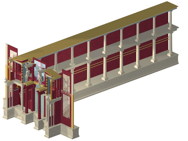
Figure 17. 3d "stage structure" from above with extruded rear portico
Viewing the 3d structure with "regular" perspective, the same seen in figure 11, shows the resultant column configuration differing significantly to that depicted in
the wall painting (Figure 18).
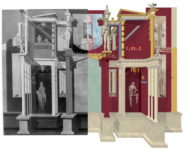
Figure 18. Comparison of the Doric colonnade depicted in the wall painting with the corrected
Vitruvian colonnade in the 3d model.
When viewed using the top and bottom level cameras used to match the perspective in the wall painting as in figures 8 and 10, it is evident that the intercolumniation of the colonnade is much more satisfactory. What does this explain about the intercolumniation? Does it suggest that columns are "real" and not flat panels? What it does imply is that there may be more to the architectural configuration than compositional aesthetics. Could the two levels be an amalgam of two different structures? Or could the two levels represent two different views of the same structure from within a theatre? Either possibility may have some relevance to the juxtaposition of the outer townscape panels, the intercolumniation seen in the inner apertures and even the size of the figures represented on both levels (Figure 18).
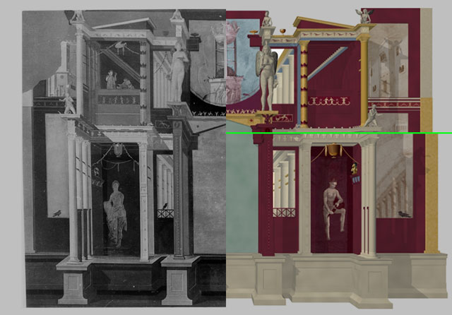
Figure 18. Comparison of the Doric colonnade depicted in the wall painting with the corrected
Vitruvian colonnade viewed as combined from the upper and lower camera perspective.
< back to The House of the Cryptoporticus contents
